This is an old revision of the document!
Table of Contents
Measuring Distance with SR-04 Ultrasound Module
The SR-04 ultrasound module can be used for many applications. For example, it can be used to trigger Halloween decorations, as car back-up proximity alerts in garages, movement alarms in homes, or as a basement sump water level alarm.
Parts List
- Arduino Uno $6
- 5mm common anode RGB LED $0.05
- Three 220 ohm resistors $0.03
- SR-04 ultrasound module $1.50
About the SR-04
There are four pins: Vcc and GND, which supply power to the module, trigger, which is used to send an ultrasonic pulse when brought high by the Arduino, and echo, which is used to receive the echo of the pulse. The time it takes for the emitted pulse to echo back to the module is what's used to calculate the distance to the object or person. The SR-04 can measure distances from 2cm to about 400cm optimally, but in most cases, using the 5V supply from the Arduino, you can measure from about 4cm to 120cm.
The pulse is a 40kHz audio tone, which is too high a frequency for humans to hear. We'll be sending a short pulse of 20ms (one fiftieth of a second) every quarter of a second or so. When the receiver hears a 40kHz tone, it will set the echo pin high.
The formula for calculating distance is time x speed of sound. And because that measures the distance from the emitter to the object and back, we will divide it by two to get the distance to the object.
So, if we have an object in front of our sensor, and it takes 5ms for our pulse to bounce off it and be detected by our sensor, we get the following formula, where distance is in cm, time in ms and speed of sound is cm per ms:
distance = time x speed of sound / 2
distance = 5 x 29.1 / 2
distance = 73 cm
Wiring the SR-04
- Plug the SR-04 into the breadboard so the pins are on different numbered rows. Do this so the sensors are facing out, away from the wiring (NOTE: this is the opposite the direction shown on the diagram)
- Use a red jumper between the SR-04 Vcc and a breadboard power bus
- Use a black jumper between the SR-04 GND and GND on the Arduino
- Use a jumper between trigger and Arduino pin 13
- Use a jumper between echo and Arduino pin 12
About Common Anode RGB LEDs
RGB LEDs come in two flavours: common anode (positive supply) and common cathode (negative). They are essentially three LEDs in one package, with either the positive or negative leads connected internally. As with all LEDs, we will add a current-limiting resistor to prevent the LED from drawing too much current and getting damaged. We are using the same value resistor for all 3 LEDs in this workshop, but if you were to do this for a long-term project you would want to calculate the optimum resistance for each LED.
Wiring the Common Anode RGB LED
- Plug the LED into the breadboard so the pins are on different numbered rows. It's helpful to plug the longest pin, the common anode, into a different lettered column (not shown on the diagram). This alleviates the issue of the long lead making it difficult to seat the shorter leads in the breadboard, and gives you a visual indication of which way the LED is oriented.
- Use a red jumper between the common anode pin (the longest pin) and the power bus
- For each of the remaining pins, plug a resistor to connect the row the pin is in to the same row, but the other side of the breadboard, as shown in the diagram.
- Use a red, green, and blue jumper to connect the end of resistors opposite the LED to Arduino pins 9, 10 and 11. It doesn't really matter which is which for now.
Coding
The code for this workshop is available here.
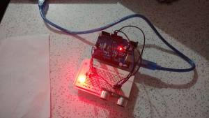
The Completed Circuit
Further resources
- Video of the sensor lighting a Halloween decoration on our Youtube channel.


